Manufacturer of Level Switch, Level Transmitter,
Detector and Sensor DITECH,LTD.
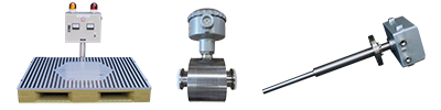
Sample testing of
electrical characteristics
Every material has intrinsic electrical characteristics. Using measuring instruments constructed in-house, DITECH has conducted sample testing and measurement since its founding. Identifying material properties through sample testing enables the operator to measure, detect or adjust to the correct level.
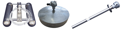
Dielectric strength test
We conduct dielectric strength testing of detectors, such as electrostatic voltmeters and electrostatic ammeters, that are used in tanks expected to operate under high-voltage conditions. Using voltage generators constructed in-house, we test detectors for the occurrence of dielectric breakdown applying appropriate voltages of, for example, 20 kV and 50 kV.
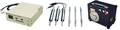
Relative permittivity measurement
Measurement is conducted using the bridge method and selecting a parallel plate system, cylindrical plate system (or other) according to the object to be measured (e.g., a powder, liquid or granular material).
In the case of a common parallel plate capacitor, its permittivity and capacitance increase by inserting a dielectric material between the two conductor plates, compared with cases in which a vacuum or air is present. The relative permittivity is determined by comparing the permittivity in a vacuum (8.854 pF/m) and permittivity with a dielectric material inserted.
Determining relative permittivity from permittivity
Relative permittivity (εr) is determined by dividing the permittivity with a dielectric material inserted (ε [F/m]) by the permittivity with no dielectric material inserted (εo [F/m]).
εr=ε/εo
Determining relative permittivity from capacitance
Relative permittivity (εr) is determined by dividing the capacitance with a dielectric material inserted (C [F]) by the capacitance with no dielectric material inserted (Co [F]).
εr=C/Co(Effective capacity only)
Electrical conductivity measurement
Conductivity transmitters are used to measure samples. It is necessary to ascertain in advance the electrical conductivity and insulation properties of the object to be measured in order to select the optimal model from our wide variety of level transmitters (and various other transmitters).
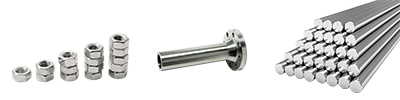
Capacitance measurement
Measurement is conducted using the bridge method and selecting a parallel plate system, cylindrical plate system (or other) according to the object to be measured (e.g., a powder, liquid or granular material).
Capacitance between two conductors (C) is determined by the following equation: C = Q/V [F], where Q [Coul] is the potential charged between the conductors and V [V] is the potential difference between the conductors.
Potential charged between the two probes of a capacitor (Q) is determined by the following equation: Q = CV [F].
Capacitance is proportional to the permittivity of the dielectric material and the area of the plate conductors and is inversely proportional to the distance between the plate conductors. Accordingly, capacitance is determined by multiplying the permittivity of the dielectric material between the plate conductors (ε [F/m]) by the area of the plate conductors (S [m2]) and dividing the product by the distance between the plate conductors (d [m]).
(εo = Permittivity of vacuum [F/m]; εr = Relative permittivity of dielectric material between plate conductors)
C=εS/d [F] = C=εo εr S/d [F]
Dummy capacitance is calculated by substituting the distance between the tank wall and the probe and the permittivity of the object being measured into the above equation and correcting detector dimensions and tank geometry.