Manufacturer of Level Switch, Level Transmitter,
Detector and Sensor DITECH,LTD.
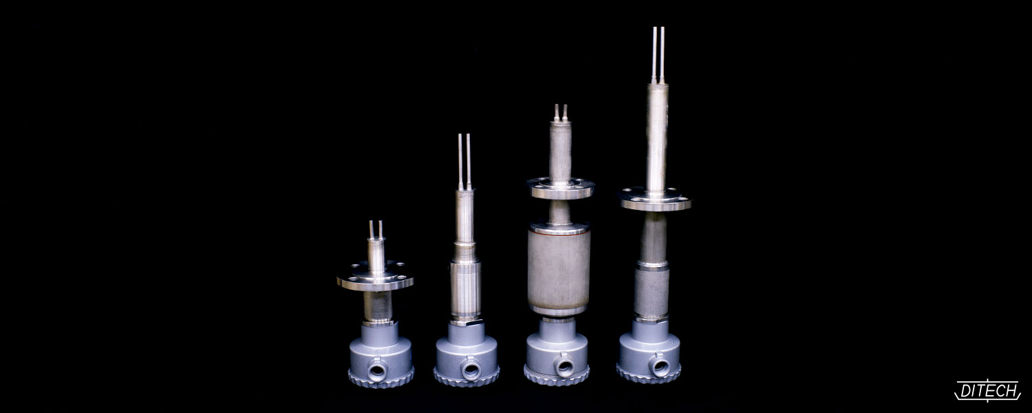
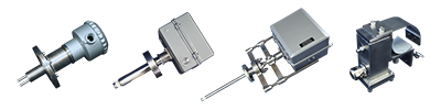
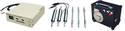
Vibrating viscometer
QBS-V
NSB-V
proof
construction
Non-explosion-proof
Intrinsically safe construction(i3nG5)
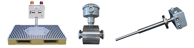
Ditech's IP model is exclusively designed for measuring the viscosity in on-line process or in-line process.
measurement
object
viscosity of fluid or slurry |
 |
 |
In a host of industrial fields, viscosity monitoring for the purpose of production-line automation is a vital requirement for more cost-effective and labor-efficient control over processing operations. The vibration viscosimeter is designed to continuously measure the viscosity of fluids on line and automatically make available a record of the measurement situation via signal output.
The vibration viscosimeter capable of Off-line use for laboratory is also available.
Click here for the page of Vibrating viscometer for laboratories.
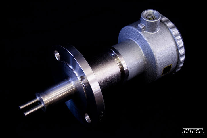
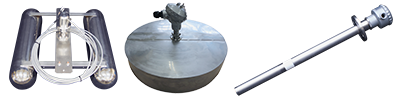
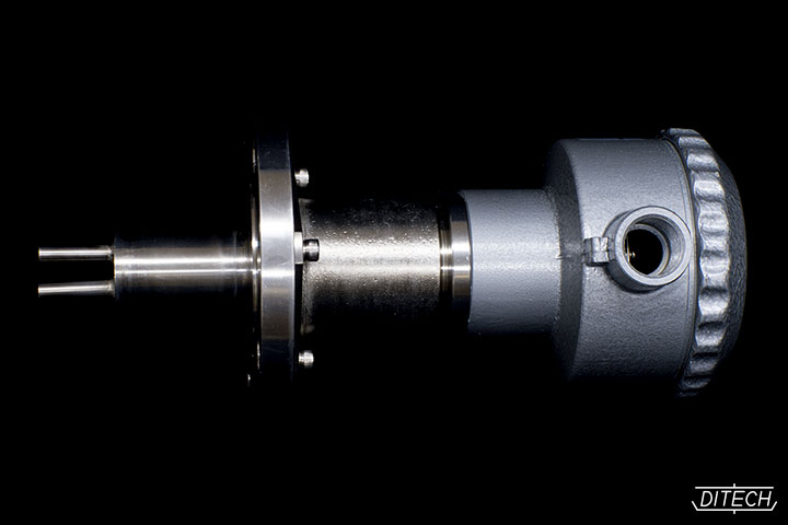
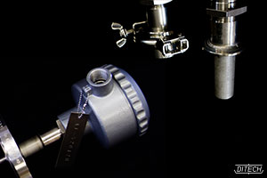
principles
The vibrating viscometer determines viscosity by allowing a vibrating blade to vibrate in a liquid and measure the resultant viscous drag. Both the shaft vibration and the detection are performed magnetically. A permanent magnet is fixed at one end of the vibrating shaft while another magnet is connected to two coils on the main unit side for the coil to the drive coil via an amplifier. The other end of the shaft (process side) is free to vibrate in the air without restriction. When the process side of the vibrating shaft is surrounded by the measured fluid and vibrational restriction occurs, the vibration amplitude is determined by the following formula.
- K: constant on the driving force and the displacement
- μ: viscosity
- ρ: density
- Ea: amplitude in air
- Ex: amplitude in the measured fluid
- C : constant derived from vibration parts
The measured amplitude varies according to the fluid's viscosity. After K is calculated using a specimen fluid for which the viscosity and density are already known, µρ can be derived by comparing Ea with Ex.
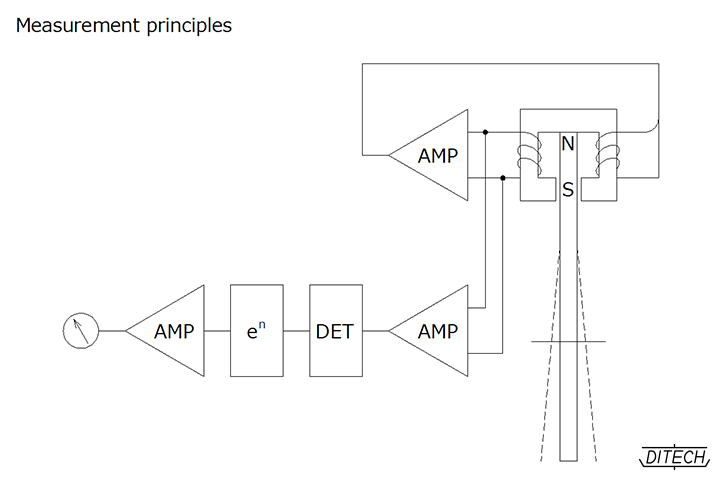
The structure of the device is shown in the figure. The vibration system consists of a positive-feedback amplification circuit loop and the drive voltage from this amplifier remains constant at all times. The shaft's vibration frequency is influenced by the fluid in which it is immersed. The amplitude of the vibration is damped according to the characteristics of the measured fluid and this change in amplitude is converted into a voltage by the detection coil. This voltage is amplified through a process of synchronous rectification and then output as the viscosity signal.
-
Measures the fluids from cryogenic temperature (-200℃) to high temperature (600℃) (Depends of the specification)
-
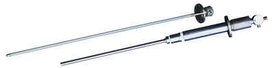
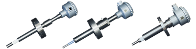
The dimensions of the device are flexibly adjustable to allow the most appropriate installation for any site.
-
The sensor consists of a welded single-body structure without a sealed section, so it features excellent air tightness and can be used even under high-vacuum conditions.
-
The sensor consists of welded single-body structure without friction parts. Two vibrating sensors capable of preventing the vibration leakage make it possible to measure the extremely low viscosity object like activated sludge.
-
A choice of sensor liquid-contact section materials are available including corrosion-resistant titanium, hastelloy, Teflon coating, etc.
-
The user can choose the measurement range freely from low viscosity to high viscosity and it is also possible to adjust the span range within the designated viscosity range.
-
The drive section and detector section do not have to be installed on the process side of the vibrating probe and the shaft can also be extended, so the device possesses high-structural flexibility as well as good heat, corrosion and shock resistance.
-
The drive system employs DITECH's original magnetic bias system consisting of a non-sliding structure with a rotating shaft, etc. This design ensures a very long working life by greatly reducing abrasion and fatigue during operation.
-
The simplified structure is relatively unaffected by external interference, giving the device excellent durability and realizing maintenance-free operation.
-
A simplified structure ensures excellent cost competitively compared with rival models and eliminates running costs.
| Measurement range | Min. range 0~5mPa・S , Max. range 0~1000Pa・S (Any other range are possible) |
| Output signal | DC4~20mA DC1~5V ※ One of the above signal |
| Input power | Model QBS-V (Model PS-0V): AC105V/210V 50/60Hz or DC24V Model QBS-V (Model PS-26): AC105V/210V 50/60Hz Model NSB-V (Model PS-25): AC105V/210V 50/60Hz |
| Power consumption | 10W |
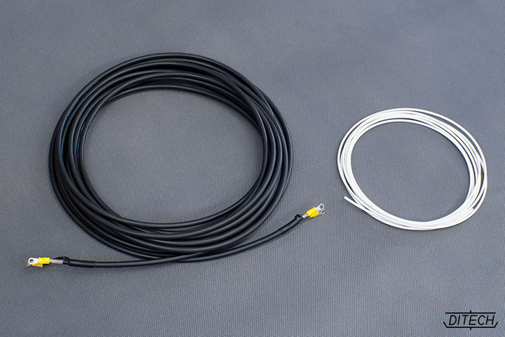
| Allowable temperature | Detector: -200℃~600℃ (Depends on the specifications) Transducer: Model PS-0V: -10℃~+50℃ Transducer: Model PS-26: -10℃~+50℃ Transducer: Model PS-25: -10℃~+50℃ Special cable: Model RG (standard type): -10℃~+60℃ Special cable: Model TEF (heat resistance use): -200℃~+260℃ |
| Allowable load | Detector: According to user's specifications |
| Allowable pressure | Detector: 5MPa (approx. 51kg/cm2G) |
| Weight | Transducer: Model PS-0V: 6.5kg Transducer: Model PS-26: 2.7kg Transducer: Model PS-25: 2.7kg |
| Size | Transducer: Model PS-0V: 216(W)×125(D)×259(H) Transducer: Model PS-26: 99(W)×130(D)×235(H) Transducer: Model PS-25: 99(W)×130(D)×235(H) (mm) |
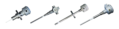
| Installation | Detector: Flange mounting Screws mounting Ferrule IDF, etc. |
| Material | Detector: SUS304 SUS316 Hastelloy Titanium, etc. Lining: PTFE Rubber, etc. Head case: Light alloy SUS304 Salt resistant paint case, etc. |
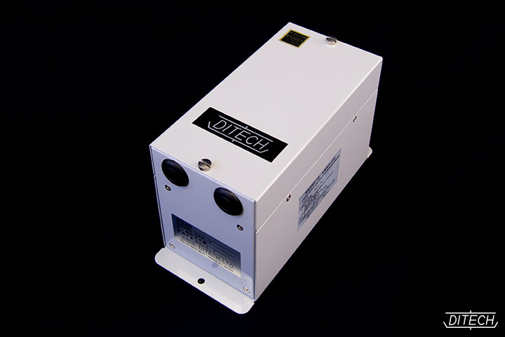
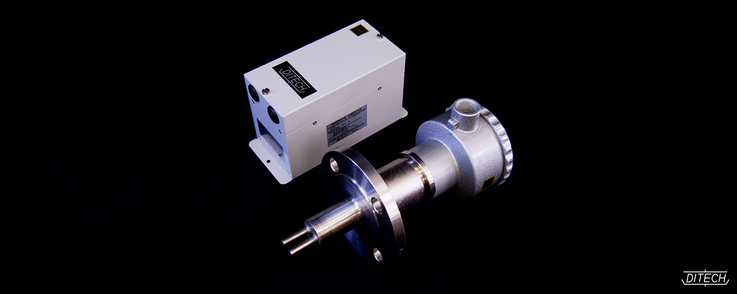
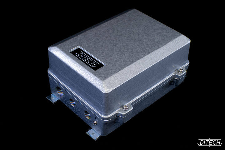
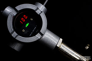
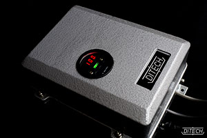
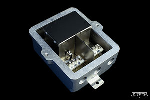
Model QBS-V
(Non-explosion-proof type)
<Separated transducer type>
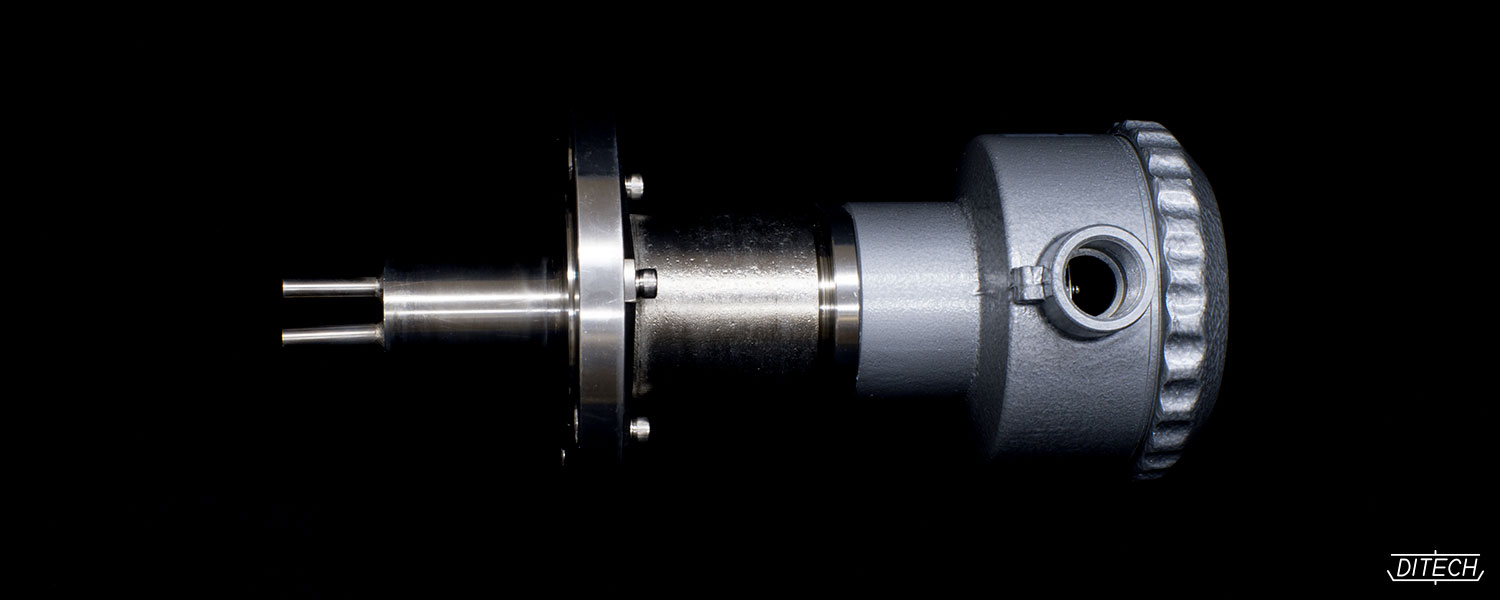
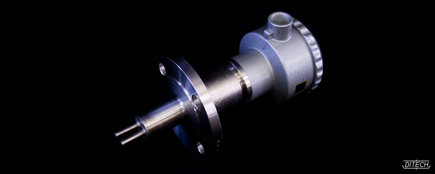
This model is composed of detector unit, transducer and special cable. Transducer suitable for indoor application or outdoor application can be chosen as per the specification.
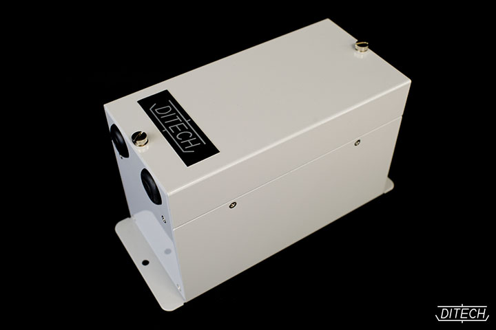
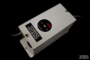
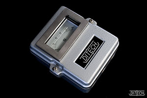
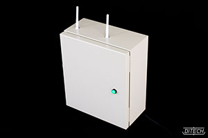
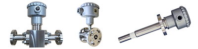
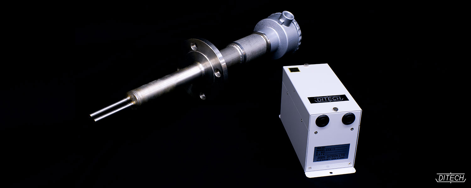
Model NSB-V
(Intrinsically safe construction / i3nG5)
<Separated transducer type>
This model is composed of detector unit, transducer and special cable.